System Architecture
Introductory Disclaimer
I am presenting the information below without aspirations to academic rigour and hopefully without any unnecessary repetition of what others have better described. I have provided links embedded in the text to all sources that I have referenced - more details may be found on the Links page. System Architecture and the systems engineering process, is an extensively debated topic about which an abundant wealth of reference material and research results can be found online. On this initial web page I am not pretending to propose anything new, but rather collecting some hopefully useful information together. Much of the motivation for doing this comes from experiences as a practitioner being confronted with repeated blank looks when asking such a harmless question as "do you know/have you heard of X?", where X is some aspect of knowledge concerning systems engineering and system architecture. This web page will evolve and at some stage be re-organised.
System Architecture and the Systems Engineering Process
In a regulated development environment the system engineering process is defined by the one or the other standard. For avionics these are Do178 for the software aspects and Do254 for the hardware aspects of the system. Medical systems are regulated by a plethora of standards, most significantly ISO/IEC 62304, 60601-x, 13485, 14971, as well as "local" stipulations such as MDR (EU), FDA (U.S.A.), etc. In other regulated environments the development process is governed by the "mother of all specifications", the ISO/IEC 61508, together with industry-specific standards, or by the ISO/IEC 26262 in the automotive industry.
The common denominator of these standards is the usage of the V model as the underlying development process. The V model started gaining currency in the early 2000s. There are countless diagrammatic interpretations of it available on the internet - and the discrepancies between these interpretations can be very interesting, Figure 1 shows the V model from the perspective of system architecture.
In the V model the system architecture is supposed to come into existence after completion of the system requirements - and these it turn can come into existence only after stateholder requirement elicitation and the subsequent definition of the system functional, non-functional and safety requirements. The implication for the juncture at which to start working on the system architecture is thereby apparently clear: only when all of the system requirements are known. As we all know, this is the classic waterfall approach.
Unfortunately life is not like that, and new "upstream" requirements (the stakeholder, functional, non-functional and safety requirements) will continue to materialise, especially in the earlier phases of a project. The establishment of these requirements resembles more an asymptotic process, with the hope that most of them will have been discovered before serious work on the system architecture starts. Therein lies the crux. At what stage should work commence on the system requirements and the system architecture when the completeness of the requirements further upstream is unknown? In other words, what is the necessary critical mass and quality of these requirements so that first steps can be taken to formulate the system requirements and a system architecture. Is this the correct way of proceeding at all?

Figure 1: System Architecture in the V Model

Figure 2: Twin Peaks Approach to making a System Architecture
A agile-oriented way of getting around this problem, so that an initial system architecture can be derived from an initial set of system requirements while further deliberations on the upstream requirements are taking place, is described by the so-called "Twin Peaks" model, shown in figure 2. It is a variation on the Spiral Model software development lifecycle (SDLC).
The "Twin Peaks" model was defined originally by Bashar Nuseibeh at the Open University, U.K. in 2001. The paper he wrote (called "Weaving the Software Development Process between Requirements and Architectures") is still available online. The essence of what he wrote was that requirements and architecture should evolve in parallel, both starting at a high abstraction level and then working steadily downwards into greater and greater detail until both requirements and architecture are considered to be complete enough to make a design and an implementation.
Design and implementation could also proceed on the same basis, but selecting the "sweet spot" is a challenge if re-design and re-implementation is to be kept to a minimum, and safety-related requirements will very often make this difficult since safety considerations affect the entire architecture and design.
Variations on this approach have also been described. One such variant is the "Zig-Zag Methodology" described in "Systems Engineering with SysML/UML" (Links: see Weilkiens)
Nuseibeh's paper is focussed on software architecture, yet the approach is equally valid for system architecture. At the system architecture stage decisions have possibly not yet been fully made about which parts of a solution will be in hardware and which in software. Answers to these questions come as the requirements are refined and architectural decisions are made.
The diagram in Nuseibeh's original paper that provided the model for Figure 2 showed "implementation dependence" increasing from left to right, going from "requirements" through "architecture". However, since both requirements and architecture should be solution-free, this dependence has been removed here.
System Architecture as a Plan
So if we are considering "system architecture" then what is a system "architecture"? What forms can this architecture take? How is "architecture" different from "design"?
The relatively new standard ISO/IEC/IEEE 24748 (2018) and the system engineering standard ISO/IEC 15288 (2015) both define system "architecture" essentially as properties and the interrelationship of these properties between themselves and between them and the context within which the system is embedded.
If we move away from standards, the difference between "architecture" and "design" is succinctly formulated by Simplicable: architecture is a plan and design takes this plan and defines one of potentially several ways (another plan) to realise the architecture. Architecture is therefore a plan focused on essential, abstract entities and structures that allow a range of designs.
For any given architecture it is possible to have multiple designs that each satisfy this architecture. In the blog-post Software Design vs. Software Architecture by LucidChart they explain what they perceive a software architecture to entail:
"...software architecture is used to organize and conceptualize a system. It includes a definition of which elements and components need to be in the system, which components need to interact with each other, and what type of environment the software needs to operate.
Software architecture defines the structure and constraints that the software developers will need to work in. It includes the documentation, charts, diagrams, and anything used to facilitate communications with stakeholders." (Copyright Lucid Software Inc.)
To complete the picture, Software Design vs. Software Architecture then differentiates software design from software architecture as follows:
"While the software architecture identifies the components and elements that need to be included in the software, the software design focuses on how the software will be built." (Copyright Lucid Software Inc.)
These statements are valid equally for both "software" and "system".
If the foregoing is to retain any validitiy then it is clear that "architecture" and "design" as activities need to be kept conceptually apart. In particular, terms like "architectural design" need to be avoided since they muddy the issue and may betray a fundamental lack of understanding camouflaged behind impressive sounding expressions.
SEBoK
If a system architecture is a plan, then what exactly should this plan contain? A good starting point to help provide answers to the introductory questions of the previous section is provided by the guide to the System Engineering Book of Knowledge, for short SEBoK(*). SEBoK also provides a good starting point for MBSE - Model-Based Systems Engineering.
The SEBoK has its origins in the aerospace and defence industries, and encapsulates the knowledge that has arisen from the regulated (as in certification) and thereby process-driven system development in these industries, particularly in respect to traceability, meaning that each aspect of the system can be traced back eventually to some stakeholder requirement(s), and quality, implying reliability, maintainability, performance, etc. System engineering as applied in various domains such as aerospace, medical technology, telecommunications, automotive and many others has resulted in domain-specific processes and vocabularies. The SEBoK has the aim to break down these differences and show that the principles that hold in one domain are really valid for all domains.
The SEBoK is over 1200 pages long, and time spent on perusal of its contents is not wasted. However, for those who want to see directly what SEBoK says specifically about system architecture then part 3, "Knowledge Area: System Architecture Definition", is the place to look.
System Definition & System Architecture
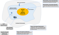
So what should be understood by the terms "system" and “system architecture” as applied to a system we wish to develop ie. the system of interest (the "SoI")? SEBoK provides the following definitions in its Introduction to System Engineering Fundamentals [SEBoK-1]:
"'System' is any set of related parts for which there is sufficient coherence between the parts to make viewing them as a whole useful. "
By definition the context of the SoI also includes the SoI itself. Since the context is a definition of the entities with which the SoI intends to interact, then it becomes clear that the "system architecture" is also going to define the interface(s) between the SoI and these entities.
SEBoK divides "System Architecture" into "Logical Architecture" and "Physical Architecture".
Logical Architecture
SEBoK makes the following key observations about logical architecture, i.e. "Logical View of the System Architecture":
"Its purpose is to elaborate models and views of the functionality and behavior of the future engineered system as it should operate while in service. The logical architecture model of a engineered system of interest (SoI) is composed of a set of related technical concepts and principles that support the logical operation of the system."
[SEBoK3]
Now the logical operation of the system is none other than the concept of operation, and clearly this must be been defined to some extent in advance. The concept of operation in turn rests on a set of use cases that need to be identified and broken down into sets of workflows, each workflow consisting of clearly defined steps.
SEBoK goes on as follows:
"The logical architecture defines the system boundary and functions, from which more detailed system requirements can be derived."
[SEBoK2
This blends very well with Nuseibeh's "Twin Peaks" approach that recommends that users, i.e. the stakeholders, should have the opportunity to provide feedback on the system model(s) that represent the architecture. Nuseibeh does not elaborate on the possible contents of an architecture. This is addressed in the SEBoK:
"The logical architecture....may include
- a functional architecture view,
- a behavioral architecture view, and
- a temporal architecture view.
Other additional views are suggested in architecture frameworks, depending on the domain."
[SEBoK3]
The setup of a functional architecture would therefore entail two principal jobs:
- determine the external logical interfaces of the SoI
- partition the SoI internally into orthogonal functional groups
This requires a more detailed look at "logical architecture" and what should be present when it has been completed. More information on this can be found on this website under Logical Architecture with SysML.
Physical Architecture
SEBoK defines physical architecture ("Physical View of the System Architecture") as:
"...an arrangement of physical elements ... that provides the solution ... intended to satisfy logical architecture elements and system requirements"
[SEBoK4]
A given physical architecture is only one possible way in which to satisfy the logical architecture and thereby the system requirements. Potentially other physical architectures will also do this, so that there is a 1-to-n relationship between logical architecture and physical architecture. The idea behind this is to produce several candidate physical architectures that satisfy the logical architecture and that can be then analysed in a trade-off to select the most appropriate physical solution corresponding to the system requirements.
So what is really involved in defining a physical architecture? Since the physical architecture is based on physical elements, then these elements must be selected such that the system requirements and the (relevant portions of) logical architecture can be satisfied. Physical elements may be hardware, software (yes, software is "physical"!), information units, and more (see [SEBoK-4, "Concepts and Principles") and the physical interfaces used to interface the physical elements. Hardware can include both mechanical and electronic elements. Software certainly includes microprocessor-based logic, and will probably also cover the hardware-software grey zone of FPGA. Physical elements may also be decomposed to aid modularisation.
The next step is to partition and allocate the functions defined in the logical architecture to the various physical elements. Again the guiding force here are the requirements, not only the functional system requirements but also the non-functional system requirements that qualify the performance, reliability, and other characteristics that the system must fulfill.
At the end of this process it should be possible to trace all aspects of a physical architecture back to the logical architecture and the system requirements. If this is not possible then either system functions have been omitted or system functions have come into existence at the physical level for which there is no justification. Neither of these scenarios is desirable.
Some of the major, and not uncommonly occuring pitfalls are skipping the logical architecture phase and producing a single physical architecture directly from the system requirements, or producing a physical architecture that is not grounded on the logical architecture. This can be compounded by allocating functions that are perceived to be necessary (but which have not really be analysed) directly on individual pieces of hardware or software. For the ( simplest of systems this approach mightwork. In the case of complex systems this shortcut simply demonstrates a lack of system-level thinking and understanding [SEBoK-4] that can potentially result in very expensive mistakes.
SYSMOD & FAS

SYSMOD (the System Modeling toolbox) [SYSMOD-1], an MBSE framework, provides a practical step by step process framework for the development of logical and physical architectures. While following many of the principles that are enunciated in the SEBoK, SYSMOD also adds new aspects and details that can be very useful when attempting the establish an architecture, and was originally presented by Tim Weilkiens in his book "Systems Engineering with SysML/UML" (first published in 2006 - see [Weilkiens-1] on the Links page). In the meantime a more concrete cookbook was published (see [Weilkiens-2] on the Links page) together with a plugin for the SparxSystems "Enterprise Architect" and Dassault/Catia "NoMagic"/"MagicDraw" UML and SysML development environments.
SYSMOD can be complemented with FAS. FAS (Functional Architectures for Systems) describes a methodology for driving the development of a functional architecture, and was first published in 2010 by Jesko G. Lamm and Tim Weilkiens (see [LammWeil-1] on the Links page). FAS defines a functional architecture as a set of related functions, with each function taking a set of inputs and producing a set of outputs according to the mathematical model y = f(x). So if a system has three functions fA(), fB() and fC(), then these could be related to each other as depicted in figure 3.
FAS defines the constructs "functional block" (containing related activities) and "functional group" (containing related functional blocks). Starting with use cases, it presents a heuristic approach for deriving activities that can then be organised in functional blocks, and then the functional blocks into functional groups. FAS does not provide a mechanistic approach to this functional decomposition; a mixture of common sense and domain knowledge must be exercised. FAS results in two aspects of a model: (1) structural in the form of activity trees, and (2) behavioural in the form of activies consisting of related actions within activity diagrams.

The FAS approach is mirrored by the SEBoK (first published in 2012). In its section on Logical Architecture; in the section of functional architecture ("Functional Architecture Model") it defines a function as transformational, accepting inputs, transforming then and then producing outputs. At a given level of abstraction a function may therefore be regarded as a black box, and the only things of interest are the inputs and the outputs; how the function is organised internally is not of interest. At a lower level of abstraction, the internals of the function will potentially be of interest. A high-level function could contain the three functions fA(), fB() and fC(). At the containing function level (here called a functional element group) the only inputs and outputs of interest are a1, ..., aN and d1, ..., dN (see figure 4), and these form the interfaces to the functional element group.
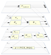
The resolution of a functional element at a higher abstraction level into separate functional elements at a lower abstraction level is termed functional decomposition. In FAS a higher level functional element can be defined as a "functional group" or "functional block"; more information on this is located here. A multilevel example, in which functional elements/functional element groups) are decomposed successively at decreasing levels of abstraction is shown in figure 5.
It is important to note that functional decomposition makes no statement about the physical location(s) of each function. In fact, functional decomposition explicitly filters out such considerations, thereby removing the temptation of "bottom-up" thinking, and therefore has the benefit of allowing the system architect to concentrate purely on the functions that need to be present on the system at each functional abstraction level. A functional architecture resulting from such functional decomposition will also retain its validity over a much longer time than a specific physical architecture.
The definition of the input and output information constituting the flows to and from each function and thereby implicitly the nature of the functional transformation results in the definition of its interface. The definition of the inputs and outputs of a function is nothing other than the definition of the context of the function. At the topmost level the "function" is the system of interest that needs to be developed.
If the system of interest is regarded as a huge "function" then the determination of the intrface(s) to this function is equivalent to the determination of the system boundary, and this leads directly to the initial activities necessary for coming up with a system architecture. The system context contains not only the system itself but all other entities (actors, external systems, etc.) that propose to interact with system of interest, and these form the stakeholders of the system.
Standards related to System Architecture
Perhaps it is a good idea to explain the "related to" in the title of this subsection.
On the one side there is "system architecture", the "plan" that should come into existence to specify how a system could be built. On the other side the question that must be answered is what premises will be used as the basis for this architecture. In other words, what is the justification for the chosen system architecture so that it does not appear as a collection of arbitrary decisions?
The framework for this chain of proof is the subject ISO/IEC 42010. The current second revision was issued in 2022 and has significant changes compared to the first revsion from 2011. This standard also derives from the IEEE 1471 which was published in 2000.
Standards defining the system & software engineering process, in particular ISO/IEC 15288 (2015) and its predecessors including IEEE 1220, make explicit reference to the usage of ISO/IEC 42010 when defining the architecture step.
It is important to note that ISO/IEC 42010 does not prescribe how an architecture should be represented. SysML and/or UML are one of the means that can be used for this purpose.